


Linear actuator helps to test railway points

An innovative system for testing railway point-changers using a linear actuator has cut testing times by two thirds while enhancing operator safety.
The actuators that switch railway points are safety-critical components. They perform the simple task of moving railway tracks, but must do so safely and reliably despite the high dynamic forces. Points-changers used in the UK operate from 110V DC supplies with a “throw bar” that moves the rails, exerting a force around 3kN. The sideways axial movement is created by a ballscrew that is driven by a DC motor, and the position is monitored using safety relays.
Proof that these actuators meet exacting railway standards was one of the main functions of a new test system developed by QM Systems, based in Aldershot. The company was also able to cut the time needed for the tests by a factor of three, thus reducing the operator workload and increasing safety.
QM faced the challenge of finding a method of testing point-changers that would be credible to a conservative and safety-conscious market. The test system had to be accurate, and capable of recording and reporting measurements precisely. The test process also had to be faster than the 1½ hours previously required, yet had to provide a step change in safety with a minimum of manual handling. It also had to be capable of testing both trackside and in-track changers, in old and new designs.
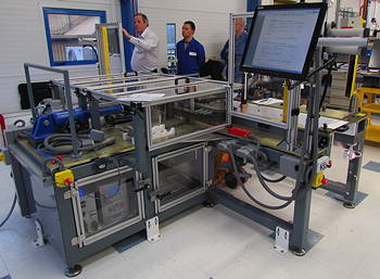
The system that QM has devised connects to points-changers that are brought in on wheeled trollies. The points-changers are located accurately on dowel pins, followed by connecting the throw bar mechanically and making electrical connections to the motor. External resistance to the throw bar is provided by a motorised ballscrew linear actuator, controlled to deliver a programmed stroke/force profile.
The points-changer is zeroed and then driven to the closed position. Stroke measurements are made using an encoder, with the stroke defining the changer model for the test report. The operator adjusts the torque-limiting clutch in the changer manually to trip at a force that is dialled up on one of two touchscreen operator stations that run on National Instruments software. The electrical functions of the points-changer, including the safety limit switches, are tested automatically.
The Servomech actuator used for the QM application has a dynamic rating of more than 10kN and a linear speed of 78mm/s. The device, supplied by Lenze, incorporates a ballscrew mechanism which allows continuous operation and low backlash. The actuator is fitted with an asynchronous AC motor with an incremental encoder and blower, allowing continuous operation at low speeds. The motor is driven by a Lenze servo inverter which can deliver controlled torque and force at zero speed. QM is using a load cell between the actuator and a bar which simulates the moving rail, fitted on linear bearings to avoid side loads to the load cell.
“The key factor to the success of the test system is a complex control algorithm that is used to simulate a rail,” explains QM Systems’ managing director, Nick Field. “It is possible to program any load up to 25KN, although 4kN is often the simulated load used. The drive runs in servo mode and particularly clever programming of the PID control loop has been applied.
“Effectively, this makes the actuator into a constant-force spring opposing the force of the throw bar – a spring that can move in either direction through a stroke of up to 150mm,” he continues. “Under test, the points-changer starts from standstill and moves through the stroke in three seconds, while the actuator delivers a constant resistive force.”
According to Field, “one of the problems we solved was the unpredictable nature of the mechanics. This was overcome by the flexibility of the drive software”. The PID loop was fine-tuned using the function blocks in Lenze’s L-force Engineer software.
The test system gives results in the form of a two-page datasheet that includes the measured forces, the settings for the torque-limiting clutch, and all the electrical characteristics.
As a result of the easy handling, the QM system has cut testing times from 1½ hours to 30 minutes. Only one operator is needed, instead of the previous two. Comprehensive guarding with light beams and safety interlocks, together with elimination of heavy lifting, ensures the welfare of the operator. The success of the machine has opened the door for further similar test systems worldwide.