


Drive-based safety offers many benefits
Building safety functions into variable-speed drives offers many attractions over using traditional external hardware and software. Matt Handley, Siemens product manager for continuous motion, explains to Drives & Controls how drive-based safety works, and highlights its benefits.
Safety installations are increasingly being implemented within drives systems rather than having to use dedicated safety equipment. The advantages for end-users include: reductions in wiring and the amount of hardware that needs to be installed; savings in space inside cabinets; and more flexible safety concepts that make it easier to upgrade machine safety at a later stage.
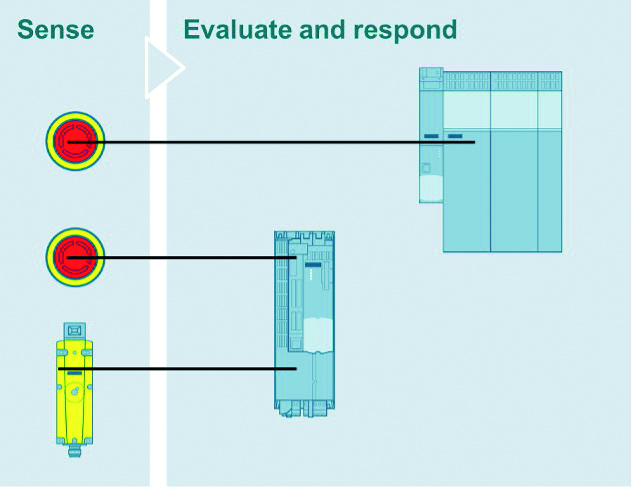
Figure 1: One way of implanting drive-based safety is locally via the drive’s terminals
To implement a drive-based safety system, users first need to perform a risk analysis and to minimise the risk in accordance with the appropriate standards. They can then design the safety functions and select their components, using, for example, the safety evaluation function in Siemens’ TIA selection tool. Following commissioning of the drive, a safety acceptance test should be performed. Here, a tool such as Sinamics Startdrive Advanced can provide assistance and generate protocols automatically.
The drive does not need to be connected to a higher-level system to implement a drive-based safety system.
Various control concepts are possible, ranging from simple local safety control via the drive’s terminals, to using an F-PLC with a Profisafe connection.
The Simatic LDriveSafe library allows safety integrated functions to be controlled easily via Profisafe.
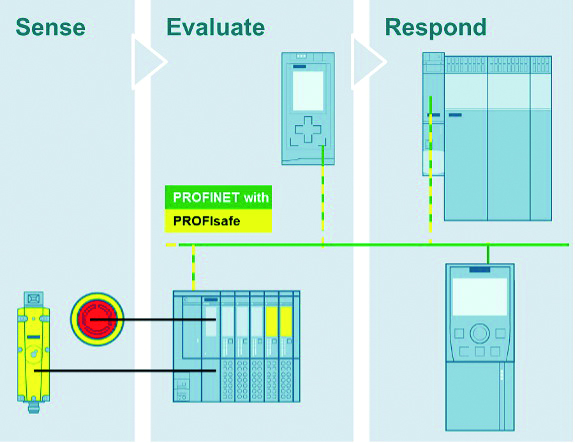
Figure 2: An alternative way of implementing drive-based safety is via an F-PLC and a Profisafe connection
Version 17 of TIA Portal implemented a new function known as safety activation testing. Since version 15, it has been possible to perform a safety acceptance test that validates the correct safety parameterisation for the integrated drive safety functions. This could, for example, check and test whether the braking ramps, and the limitations and fault reactions, have been set correctly.
The new safety activation test validates the complete safety control system from sensors to actuators. It is now possible to test, and gain a clear understanding of, whether:
- every drive selects the correct safety function when a safety sensor is activated;
- all safety functions are realised to minimise risks; and
- whether there are any wiring errors for the safety sensors.
Saving time and money
Depending on the safety functions required, users can save a lot of money by using the safety functions built into a drive rather than relying on conventional external safety systems.
Using traditional drives without built-in safety requires additional hardware safety components such as safe speed-monitoring devices. For a drive with integrated safety functions, all that is needed is a safety software licence for the drive. The reduced wiring effort and savings in cabinet space mean that the time needed to set up built-in safety functions is also reduced compared to conventional safety designs.
Naturally, some users are worried whether a safety system implemented in a drive will be as reliable and effective as one based on dedicated safety hardware and software. One form of reassurance is to ensure that the integrated safety functions comply with, and are certified to, the relevant standards – IEC 62061 and EN ISO 13849.
Wizard
Software tools – such as the safety acceptance and the safety activation tests in Siemens’ TIA Portal – can also help to ensure that the safety functions have been parameterised correctly. The acceptance test is a wizard that guides the user step-by-step through each of the drive’s Safety Integrated functions and checks whether the parameterisation is correct (as well as testing safety parameterisation within the drive).
The new safety activation test additionally checks the complete control chain from the sensor through the F-PLC failsafe program to the reaction in the drive. Both tests generate a standard-compliant test protocol automatically which the user can sign and add to the machine documentation. This gives the engineer the reassurance that all safety functions have been implemented and tested correctly*!
If the requirements of an application change after a drive-based safety system has been implemented and commissioned, its configuration and operation can be updated to satisfy the new requirements.
Licence
Because the safety functions are implemented within the drive and enabled via a licence, users can simply add or adjust the machine safety functions at a later stage without needing extra cabinet space or additional hardware.
Drive-based safety systems complement the trend towards industrial digitalisation and the use of technologies such as edge computing and artificial intelligence in manufacturing. For example, the safety functions of a machine can be tested and evaluated using a digital twin of the machine, even before the actual machine has been built physically.
There are, of course, situations where drive-based safety may not be the most appropriate safety technology to apply in an installation. For example, if you are using motors that are not controlled by frequency converters, traditional approaches to implementing safety functions may be more suitable.
These are still relatively early days for drive-based safety, and the future could open up new possibilities for the technology. For example, there are exciting developments in areas such as robotics where Siemens’ Simatic safe kinematics offers distinct safety categories.
Closer fences
Safe zone monitoring detects collisions between a robot and previously modelled zones so that the robot can be stopped before it reaches a protective fence, for example. The software can reduce the space/area requirements needed for a robot cell, because it allows the protective fence to be installed closer to the robot.
With the aid of safe zone monitoring, a robot does not need to be stopped as long as the operator is far enough away from the hazardous area. The closer the robot approaches to the operator, the more its velocity is reduced and monitored safely by the built-in velocity-monitoring functions.
Monitoring velocity
The velocity can be safely monitored not only at the tool centre point, but also at any point on the robot, the tool and the workpiece. The robot can therefore perform other tasks at a distance from the operator and, for example, continue to process workpieces or to perform handling tasks. The safe kinematics software therefore increases the availability and productivity of machines.
In the case of robots being used to perform welding or jet-cutting tasks, operators can remain in the hazardous area of the robot during set-up or when teaching the robot tasks. To protect operators from injury, the welding or jet-cutting task must not start until the welding pistol or cutting device is at a certain angle to the floor – vertical, for example. This is checked by the safe orientation monitoring function integrated into the safe kinematics software package.
Safety functions built into variable-speed drives are changing the way that machine safety is being implemented in today’s factories.
* This is demonstrated in episode 4 of the Safety To Go video series